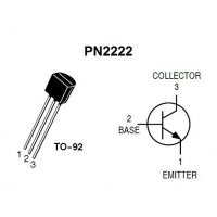

If you connect it as a Vbe multiplier, say with 5:1, and average many measurements you might be able to get a usable resolution of about 0.5☌. Sensitivity will be about -2mV/K so with a 5mV resolution ADC you’ll have 2.5 degrees C resolution, not great. It will require calibration (say at room temperature and 0☌ in an ice-water slurry. Therefore, any output on the master that is to be received on an input on the slave should have appropriate 5V to 3.3V level shifting circuitry.If you connect the transistor as a diode and bias it with a reasonable current, maybe a couple hundred uA, you can read the voltage. One thing you should consider is that the Leonardo’s GPIO outputs will be 5V, whereas the RP2040 operates at 3.3V and its inputs can’t tolerate anything above that. If you use a 100kohm resistor, the maximum current that could be forced into a pin (at 5V) would be 50μA, which is highly unlikely to cause any damage. Because the inputs themselves have a high impedance, the inline resistor shouldn’t affect the signals but will protect any inputs from excessive current.

Before powering down the slave, the pins on the master should again be set as inputs.Īnother thing you can do, if you’re just sending digital signals back and/or forth, is put a fairly high value resistor between each output and corresponding input. After the slave has been powered up by the master, you then set the pins as required. If the master has other inputs or outputs connected to the slave to monitor or control the slave then you just have to be a little careful.Īny pins on the master that connect to the slave should be set as inputs (without the pullup enabled) while the slave is powered down. If the master (Leonardo) that’s controlling power to the slave (RP2040) is only used to power it on and off then there’s no problem. So you have to be careful when designing what connects to the slave chip to cut off any leakage current sources. (Note that you have to make sure that the GPIO is actually capable of providing the required base current.) The “wasted” power that the GPIO pin has to provide to the base for a BJT versus essentially no power for the gate of a MOSFET.The collector-emitter saturation voltage (Vce(sat)) of a BJT versus the drain-source on resistance (Rds(on)) of a MOSFET for how it affects the actual voltage that the load receives and the power that the transistor has to dissipate.To decide whether to use a MOSFET or a BJT you have to consider: This is worst case, so you may end up feeding up to about 7mA but this is not a problem other than wasting some power.

Maximum Vbe(sat) is 1.2V and the output of a GPIO might be 4.5V, so To calculate the resistor value, you subtract the base-emitter saturation voltage (Vbe(sat)) from the input voltage then use ohms law.
#PN2222 TRANSISTOR THRESHOLD SERIES#
If the base is being driven by an output at a fixed voltage you need to put a resistor in series with the base to limit the current to what’s desired (5mA). However, to be safe it’s better to have a fair bit more than that, so maybe 5mA. To have 100mA flow from collector to emitter, you would need to put 100mA÷35=2.86mA into the base. To saturate one (switch it fully on) you have to feed at least enough current into the base, proportional to the gain (Hfe).įor instance, the 2N2222A can have a gain as low as 35 in some instances. BJTs are current amplifiers (not voltage as a FET is). 2N2222 BJT: 30ns switch on, max 150 mA, Gate ThresholdĪ BJT (Bipolar Junction Transistor) doesn’t have a gate.


 0 kommentar(er)
